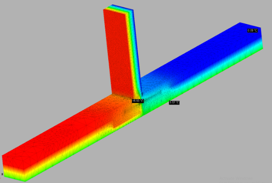
Fig 1: 3D thermal model showing the temperature gradient of a concrete slab (with edge insulation) with steel penetrating the slab edge insulation. © 2024 Sustainable Engineering Ltd
Insulating the edge of a concrete slab is very good for thermal performance. However, there are situations that require penetrating that insulation and it’s typically done with steel rods. That solves a structural problem and achieves an engineer or architect’s goal. But steel is of course a great conductor and the resulting thermal bridge is an issue for the Passive House designer.
In projects that have come across our desks, such penetrations of edge insulation have been needed to create connections to concrete foundations outside the thermal envelope (typically garages) or wing walls. We’re seeing Passive House designers either not accounting for the heat losses through those thermal bridges or accounting for it very conservatively. Being conservative keeps your design safe with regard to certification maximums but when you get too conservative, complexity and cost likely increase. It’s always best to have accurate data to rely on.
Engineer Alvin Abon has produced a 3D thermal bridge calculation of one of the most common details, a 16mm diameter (D16) steel reinforcing bar penetrating a 50mm XPS slab edge. (This is where curiosity takes you, when you have the skills and the software to do advanced 3D modelling!) Alvin modelled two scenarios, with and without the rebar.
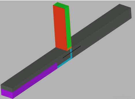
Fig 2: 3D model showing the materials in this detail: concrete slab (with edge insulation) with steel penetrating the slab edge insulation. © 2024 Sustainable Engineering Ltd
The result of the model illustrated in Fig 1 is a chi value of 0.022 W/K for each steel rod for this configuration.
This is why we model, to test our educated guesses. My hypothesis was the steel thermal bridges would be more thermally conductive than this. Do note it’s 0.022 W/K for each steel rod—it’s not unusual for this detail to involve 50 reinforcing bars. While even the combined impact is small, this detail will matter if your design is right on the line with regard to heating or cooling demand or load.
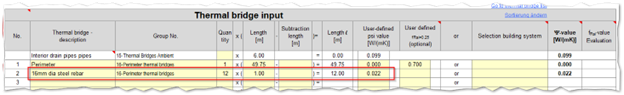
Fig 3. How to enter these numbers in the PHPP Areas worksheet
Here’s how to enter the figure into PHPP (Fig 3). For a point thermal bridge, the length is always 1 metre. The quantity is the number of steel rods penetrating the edge of the slab. This thermal bridge is set to Group 16 a perimeter thermal bridge as the slab edge heat transfer losses/gains are buffered partially by the ground.
Before you rush to use this figure, please read the following caveats. This chi value only applies when your slab edge looks something like this detail below: you have an adjoining piece of concrete (garage, wing wall or other) that isn’t drawn in the slab edge calculation.
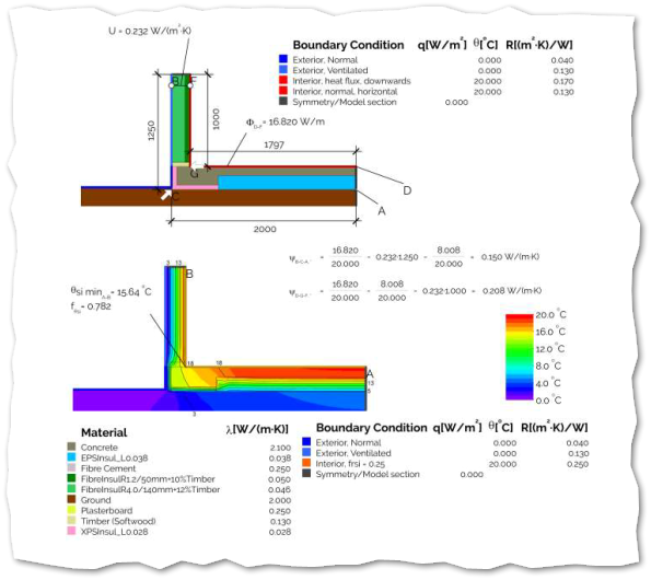
Fig 4. Source: High-Performance Construction Handbook: Junction 29 EWFS External Wall to Floor Slab 140/45 timber wall to slab on ground with continuous under-slab and 50mm overhung edge.
A further disclaimer: the calculation above is based on 16mm diameter steel through 50mm XPS (R1.79), the most common configuration. Our result is conservative and is still safe to use if your design differs in the following ways:
- steel reinforcing with a diameter less than 16mm
- reinforcing is stainless steel, or
- the slab edge has less insulation (eg it’s EPS instead of XPS).
Do not use the 0.022 W/k chi value if the
- steel penetrations are of a larger diameter
- slab edge insulation is thicker or has a higher R-value, or
- benefit of the adjoining structure has been included in the slab edge thermal bridge.
If you’re in this situation, I strongly recommend you get advice from your certification team early. There are a range of options for how to proceed.
One option is to remove the thermal bridge entirely by using a glass fibre reinforcing product such as Mateen bar. This is a more expensive product compared to regular steel but there is no need to model it because there is no thermal implication. Just include it in the structural specification and make a note for your certifier.
Previously, the only information to consult has been the graph below from PHI. Its applicability to New Zealand building practice is pretty limited: it’s a different assembly, material, insulation material and quantity of insulation compared with what’s typical in New Zealand. But it was all we had to go on until now.
Very interestingly, the 3D thermal model Sustainable Engineering Ltd produced fits neatly on the curve (for the worst performing combination of materials and 16mm diam. steel). Note the red x below.
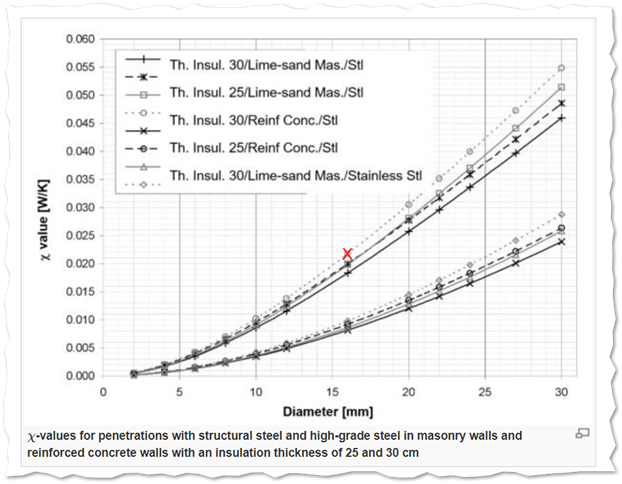
Fig 5: Early research from PHI on the impact of punctiform penetrations. Source: Passipedia. Note in that article where they say ‘high grade steel’ then mean stainless steel which has a lower thermal conductivity.