Every indoor environment would be improved by mechanical ventilation systems delivering the ideal rate of fresh air but it’s non-negotiable when creating the air-tight building envelopes that characterise Passive House structures.
MVHR systems are not plug-and-play. Architects and Passive House designers need to start thinking about ventilation strategies and requirements right at the concept stage. In this article, I’ll run through some key concepts based on what the Sustainable Engineering Ltd team has seen work (and not work) on scores of New Zealand high-performance buildings. My particular focus is on good acoustic performance. Following this advice will save your clients money, massively reduce the risk of drama or mistakes on the construction site and create a better outcome for the building’s occupants, now and in the decades ahead. I’ll also touch on good and bad install practice and how to measure sound levels for the purpose of Passive House certification.
Planning good acoustic outcomes is an important part of system design. But what’s good for airflow, and ventilation outcomes in general, is good for acoustics too: it all goes together. Excessive noise at the terminals can be a sign of more systematic problems. That’s hard to fix once construction is completed, so focus on preventing problems in the first place. What follows is not an exhaustive list of MVHR issues designers should consider; there are more subtleties and other aspects to take into account. Lean on your chosen supplier’s expertise.
Give the MVHR system the space it needs for optimal performance
Many problems stem from trying to stuff a system into a space that hasn’t taken into account the physical requirements of the MVHR. A lack of planning at the concept stage risks a chaotic installation with excessively tight bends in the ductwork. The time to begin thinking about ventilation is at the concept stage. Ensure you’re designing service cavities with enough space for the duct runs, understand what space is appropriate for the unit and allow for the splitter boxes.
Clearly understand whether the MVHR unit you’ve specified can be installed with supply and exhaust in fixed positions or whether they are interchangeable. Different brands and models vary. In a tight space, the position of the outlets may matter.

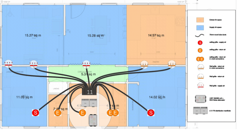
Fig. 1 Preliminary MVHR schematic in a very simple house. Duct runs will be optimised on site. © 2023 Steibel-Eltron.
In a very simple house where there is lots of space in the ceiling space, a basic layout might work fine. Otherwise, it must be coordinated with the architectural design of the building structure. MVHR ducting can’t magically penetrate giant steel beams. I’ve also seen 35mm service cavities proposed. This is not adequate! Fifty five millimetres is the bare minimum and there’s good reason to allow more; consider space for the grill housings, not just transitions through pinch points.
The first MVHR system layout should be seen as the start of a conversation between the architect, Passive House designer and supplier, not an end point. It’s not uncommon for the design to be done early in the project, typically at the beginning of detailed design. Too often, it won’t get thought about again until suddenly there’s a flurry of ordering the unit and components arriving on site and someone starts to figure out how to piece it together. Better to see that first layout as a starting point for discussion and to check in periodically as other details are developed. Suppliers know their systems inside and out and are committed to delivering the best solution possible. They are a valuable resource; work with them and listen to their advice at early stages of design.

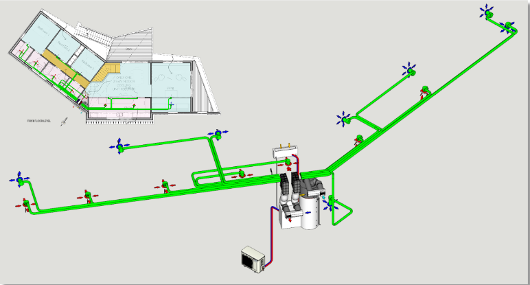
Fig 2. A 3-D schematic and floorplan for a more complex house, adapted on site during construction. © 2023 Edge Innovation, used with permission. See Bell House case study.
Design for optimal acoustics
Passive House buildings are quiet inside, thanks to the superior insulation and double or triple-glazing which block the transfer of noise as well as heat. This has some great upsides, especially in a busy, urban environment filled with unwanted noise. In a busy household or public building, the sound of the MVHR system is unlikely to be noticed. But in a quiet room, it may become apparent and it can be an issue for some occupants.
Hopefully by concept design stage, the architect or designer will know something about how the client lives, the type of environment they’re comfortable in and their sensitivity to noise. Take their preferences and comfort into account and design, specify and install the MVHR system accordingly. Decisions and actions all the way through the process will influence the level of sound at the unit and at the outlets.
Remember that decibels are a logarithmic scale. It’s a complex field; you can read more here, along with examples of different decibel levels.
There are three distinct aspects to consider when it comes to optimising MVHR acoustics:
- breakout sound from the MVHR unit;
- the noise at the terminals; and
- noise transfer around the house (via the ducting and makeup air).
Noise at the unit
The MVHR unit itself does make some breakout noise, generally about 20-25dB. Some units are quieter than others. Manufacturers do include noise levels in the unit specifications but one expert I consulted warned this information may not be useful. It’s often data provided by the fan manufacturer, which does not take into account what the fan is housed in. Note that suppliers aim for the fan to be running at 50-60% of capacity during normal operation. This reduces breakout noise.
This caution from Fantech is also useful. “However, published dB(A) sound pressure levels should be used for comparative purposes only, they are not designed to reflect actual installed noise levels. The assumptions that are used to calculate the dB(A) are rarely replicated in real life situations and, therefore, published dB(A) values will not necessarily represent the actual noise levels that may be experienced on site.”
The best place for the MVHR unit is in an accessible cupboard, or a room where noise levels don’t matter, such as a utility room or laundry. (If fitting in tight spaces, ensure your design complies with the manufacturer’s specification for clear space around the unit.) Avoid mounting the MVHR unit on the opposite side of the wall to the head of a bed for instance.
What about a silencer? Many MVHR systems designed for Passive House have duct splitters (aka distribution boxes) that also perform as a silencer. If the system you’re specifying is not certified as a Passive House component, this may not apply. Silencers (properly “noise attenuators”) will deliver about 15-17dB(A) of noise reduction but it can be as much as 29dB(A). It’s much harder to find data on silencer performance compared to MVHR performance.
Noise at terminals
Extract terminals are slightly noisier than supply air terminals. Extracts show up in kitchens and bathrooms, generally rooms where people are less sensitive to noise. But the typically hard surfaces found in these rooms will bounce sound around rather than absorbing it.
Take some care where the extract terminals are located in a room. The most noise will always be heard directly underneath the terminal. Having an idea of furniture layout and patterns of occupancy will help guide ideal placement. You don’t want terminals over noise sensitive locations like beds, a work desk or a nook designed for quiet reading or study.
Ducting
Give some thought as to where the ducting itself runs. Do duct runs require cutting a hole between an acoustically sensitive space such as a bedroom and a noisier space like a bathroom or TV room? This can cause acoustic bypass, where unwanted noise leaks into the quieter room via the ducting. You can prevent these highways for sound by specifying that all duct pathways be insulated.
Ensure that the installer does not use flex duct. We’ve provided advice previously about why it’s a bad idea; in addition, it will generate more breakout noise. The ribbed interior creates turbulence, which means more sound. There is also an increase in friction inside a bumpy flex duct, meaning the fan has to run faster (and is therefore noisier) in order to provide the required airflow. It’s also really easy to accidentally damage, and a damaged duct is a noisy duct.
The calmer the air flow through the ducting, the less noise produced by the system for a particular duct. Many things contribute to slower air flow: the diameter of the ducting, the duct material, the shape of the curves (large gradual bends help eliminate turbulence and therefore noise), the lengths of the run and the form of the terminal.
Makeup air
Mechanical ventilation requires that air can circulate readily throughout the entire house. Easy when doors are open, harder when rooms are closed off. The standard solution is to undercut doors by 10mm. This is definitely the easiest way to transfer air between rooms but it can mean that you can hear what is going on in the bathroom (or bedroom) even with the door closed. We know of one case where clients with teenagers very firmly ruled out using door undercuts again when they commissioned a second Passive House home.
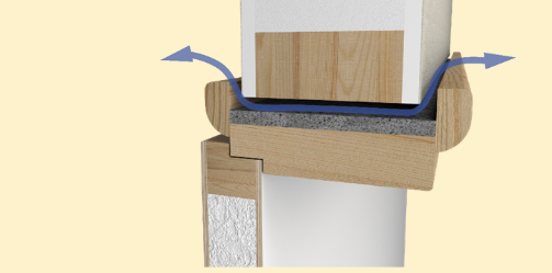
There are alternatives, such as providing a path for air transfer over a door frame, which involves extra carpentry work on-site; see Fig 3 below. (See an elaborate handcrafted solution that involved building a bypass mechanism into the door itself, relying on a series of right angles for acoustic attenuation.) See this document for simple diagrams of transfer grilles and jump duct grill alternatives.

Fig 3 A cross section through the door frame of an acoustic door overpass over an internal door. This is an acoustically-superior option to a door undercut. The black foam is an acoustic foam from Formans. It’s essential to maintain a 10mm gap throughout the path. © 2023 Sustainable Engineering Ltd
Good installation practice
We are aware of a handful of poor quality MVHR installations in some New Zealand projects that have compromised the efficiency of the system and made its operation noisier than it should. Here are some best practice guidelines for running ducting.
- Tight bends increase noise at the terminals, gentle bends and loops are better. Think S-shaped runs not L-shaped.
- Short duct runs increase sound pressure at the grille face due to excessive pressure/velocity. It can be worth installing a longer duct run in a loop if it terminates in a noise sensitive room. We’ve had some MVHR designers recommend keeping all the ductwork lengths similar and looping the excess duct length in the ceiling. This can help with acoustics and balance airflow distribution.
- A taller duct terminal creates less turbulent airflow and therefore less noise. Terminals need an absolute minimum of 100mm to the face of the finished ceiling, but 150mm allows for better acoustic performance. If your service cavity between the gypsum ceiling and air control layer is only 50mm you will need to design in a recess or pocket in your air control layer.
Commissioning
The Passive House certification standard (section 2.4.4 Noise protection) sets a maximum sound level in typically occupied rooms in residential buildings of 25 dB(A) for supply air and 30 dB(A) for extract air, all measured at typical MVHR flow rates. The standard says that a sound protection calculation might be required by the certifier if s/he is concerned about noise levels.
Most of the certified MVHR systems contain sound attenuators. That, combined with the good practice outlined above, can be expected to result in appropriate sound levels. Sustainable Engineering Ltd’s team generally don’t want to require sound protection calculations for certified MVHR systems containing sound attenuators: sound protection calculations are typically done by acoustic engineers and they are expensive. Instead, submit acoustic measurements recorded at the MVHR terminals during commissioning. The PHI MVHR commissioning sheet has a space to record the results. This is good practice and ensures clients are getting what they paid for.
As certifiers, if we see a design where we think sound levels may be an issue, such as one without a sound attenuator or a novel design, we will require sound protection calculations as well as sound measurements.
An acceptable method to measure the acoustic levels under normal operation can involve just a smartphone and an acoustic measurement app. First, turn the system off, close external doors and windows and have tools put down, in order to take a reading of the background noise. Anything below 25dB(A) is a green light to proceed. If background noise is above 25dB(A) because of consistent, ongoing noise such as a busy road outside, this should be noted on the commissioning sheet (there isn’t a specific location for this). If the noise source is temporary but can’t be abated, then come back to take acoustic measurements at a quieter time. Take readings at each terminal, holding the phone at approximately head height beneath each vent. Note the readings down on the commissioning sheet. Ensure homeowners are clearly briefed about the need to clean and change filters and the frequency intervals. If the filters get clogged, the fans will be working harder to pull fresh air through the system and that means more noise. See more about filter changes (and the importance of cone filters on extract vents) here.